The technique which I will try to briefly describe in this post is often referred to as dithering. The term according to Wikipedia comes from the old English word “didder”, meaning to shiver, shake.
During continuous to discrete-time signal conversion a so called quantizer component is used. Quantization in signal processing is a process of converting the information from a fine continuous-time (analog) signal to one represented in finite amplitude steps by sampling. It is important to mention that time sampling (ideally w/o quantization) does not generate noise and if one ensures that the sampling frequency exceeds the Nyquist rate, then a smooth signal is again obtained and no information is lost. In reality however in a sampled system we can not save each sample with its exact value, but instead we often need to quantize (digitize) it and store it with a limited number representation (bits). Having a limited set of numbers means that in reality there would be a discrepancy between the real analog signal and the quantized (digitized) one. Here is a quick sketch showing what I actually mean:

An analog signal and its quantization
The analog signal is quantized in a finite set of steps and the error between the real sampled and the converted (quantized) values is shown in the hatched area. Now, it has been shown that with the help of oversampling techniques one can statistically increase the resolution of a quantizer by generally speaking accumulation and averaging.
My post aims to show how the effect of oversampling and therefore Signal to Noise (SNR) ratio can be increased by injecting even more noise into the system. At first glance one might say – no way! However, that’s not always the case. If the quantizer is coarse (so that no circuit thermal noise would influence it much) and if the injected noise (dither) has the right magnitude we can gain a lot. Let’s have a look at a simple and intuitive example. Here is an overview of our system consisting of a signal source 


Analog additive dither and a quantizer
Let’s apply a sinewave
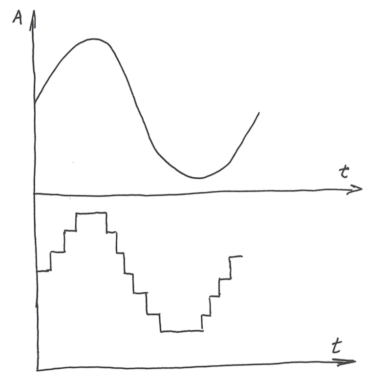
An ideal quantized sinewave
Now if we inject random uniform (a key role, to be discussed in Part 2 of this post) noise

A quantized sinewave with additive dither
It comes to ones intuition that if we try to average the samples we might actually have done a higher resolution quantization. Think low-pass filtering. However to give a very clear illustration I’ll introduce a numerical example. Consider a DC signal of 2.5 Volts and an ideal quantizer of 2 bits:

An example of DC signal oversampling with and without dither injection.
We can see that without any dither the average conversion value is still 3, while by adding dither we randomize the error and after averaging we have gained additional resolution. Obviously my 2.5V example is a bit too idealistic and there is an awful lot more to this, but I just wanted to make my trial at introducing this concept here. Some other day I will write some about analog additive and digital subtractive dither, as well as its impact on images.
