Author: Desi

VIP pass to a holograpahy lab

Greetings! I am proud to present our brand new labs at the Institute of Optical Materials and Technologies! After a whole year of construction work, repairs and various emotions, the renovated labs are finally ready for action. And for our (many…) readers exclusively, I will present our optical arsenal:

WP_20150514_11_41_55_Pro

Overview of the CW lasers lab

Our CW lasers lab is home of Coherent’s mighty Verdi laser – a DPSS at 532 nm wavelength and a maximum output power of 12 W. Right next to it is the Japanese hero from Kimmon – a He-Cd laser at 441,6 nm and 0,18 W output.

WP_20150514_11_40_53_Pro

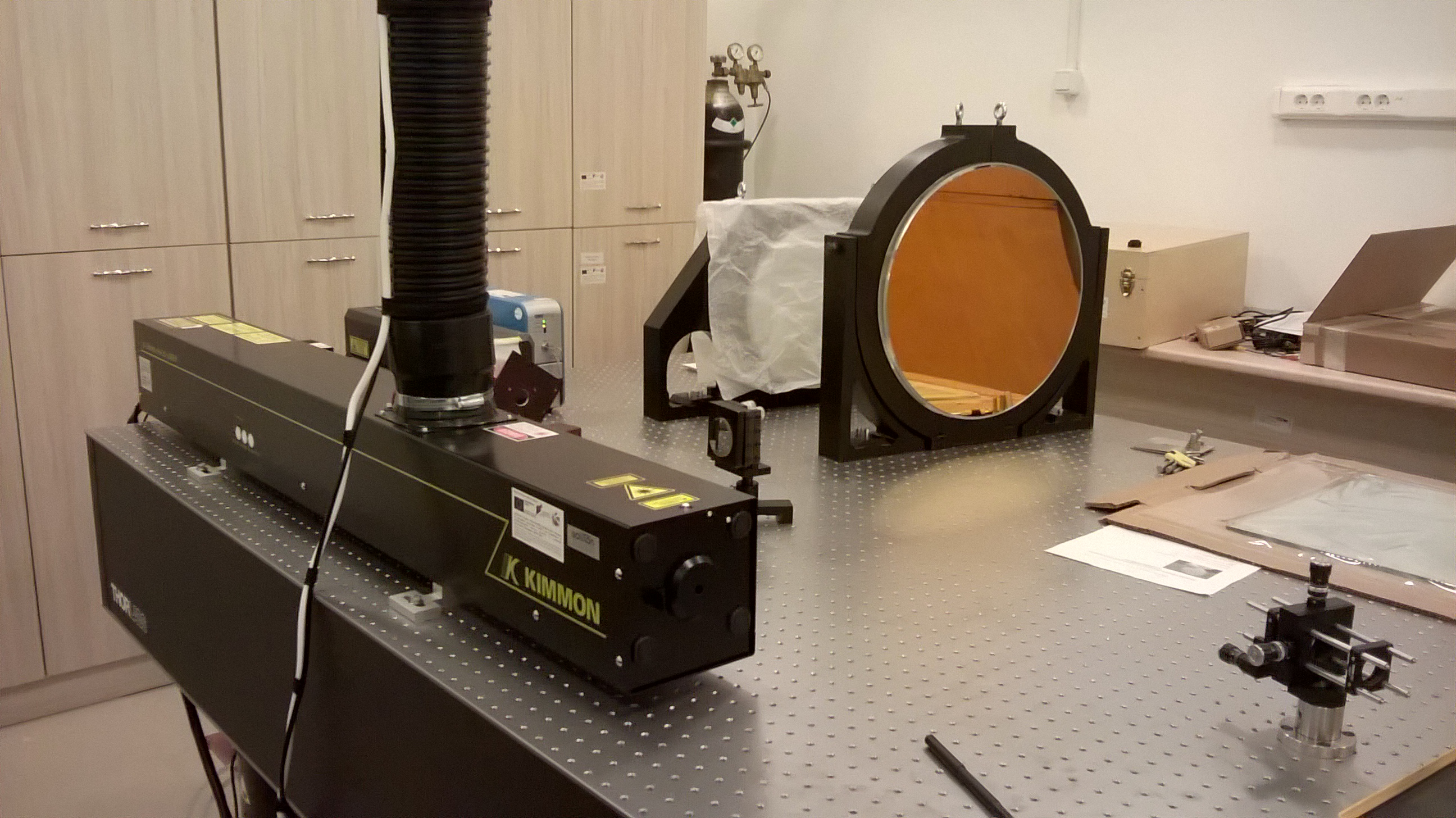
He-Cd laser and a huge mirror

We also got two laser diode systems from BWtek at 780 and 635 nm and a few more systems from Cobolt and Coherent – no need for an extensive description of everything for now, hopefully you’ll meet again with some of these lasers in a future post that will be more specific. The important thing is we got the reds, the greens and the blues covered. So a multicolour hologram, maybe, someday? It will be very exciting!

WP_20150514_11_41_17_Pro

Lots of optomechanics as well…

WP_20150514_11_41_45_Pro

These tools are never enough… And never organised

WP_20150514_11_41_02_Pro

Preparation for a holographic recording setup… You can see how huge the laser spot is and we will make it even bigger in order to “capture” the object

Apart from the CW lab, we also got a separate pulse lab, where our two Nd:YAG lasers rest for now. They are around 1 μm (I always forget the exact value) but they are mainly used for second harmonic generation. Third and fourth harmonics are also possible although weak.

WP_20150514_11_51_25_Pro

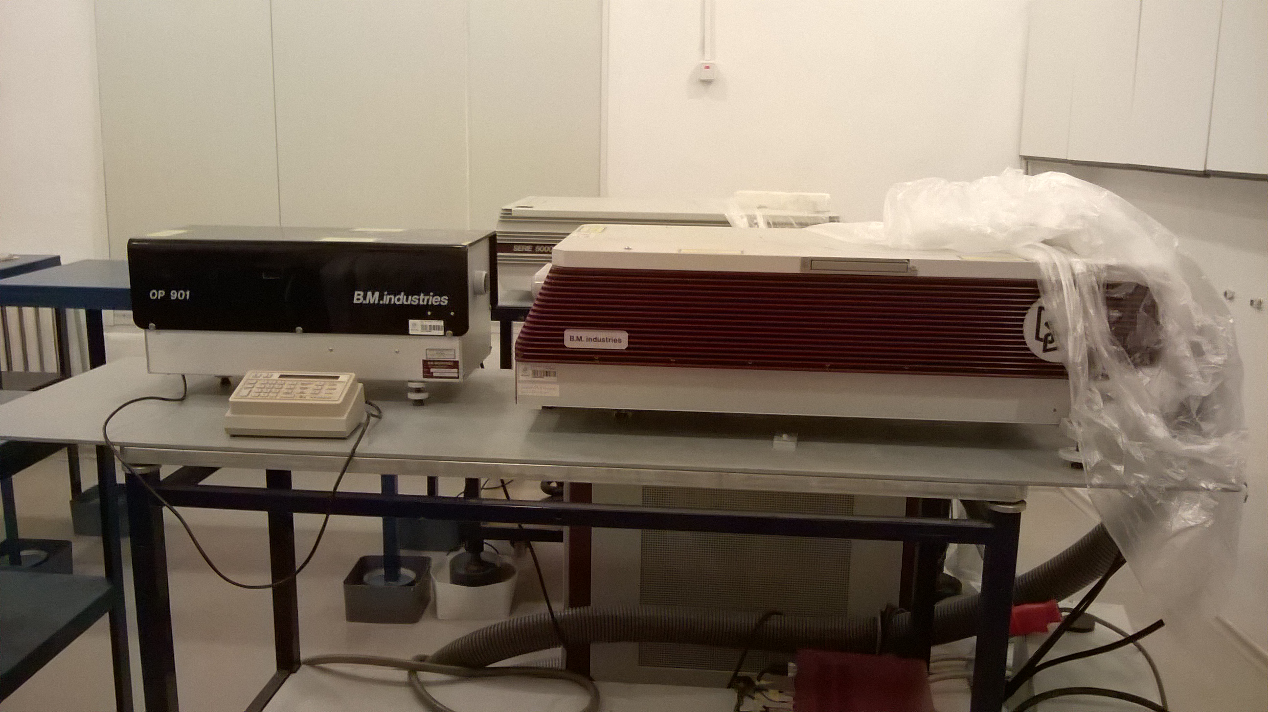
This guy is from Stuttgart (or so it says on the sticker)

Hmm, this post turned out shorter than I imagined… Sorry! I hope you liked this sneak peek of the labs and I will be glad to show you some *real* work soon. In the meantime, here’s an abstract-spectrum-thing painting I made for our new office rooms at the Institute – if my colleagues like it, we may even hang it on the wall:

The hyperfine structure of cesium

Today in the lab of atomic spectra we built a setup for observing the hyperfine structure of cesium. It is a big deal for atomic clocks as they use this transition to “tick”. It is also a very very tiny and fine effect (as its name suggests) so it’s pretty exciting that we can see it with such simple setup.

First, here is a brief description of atomic structure notation. The source of the text and picture is http://webphysics.davidson.edu/Alumni/JoCowan/honors/section1/THEORY.htm

The electrostatic attraction between the electron and the nucleus could be described by the principal quantum number, n. The combination of l and s gives an electron’s total angular momentum, J. Magnetic coupling between the electron’s orbit and spin causes an energy splitting between levels with different J called the fine structure. The fine structure is split again into the hyperfine structure denoted by the letter F. The hyperfine structure is due to a magnetic coupling between the electron’s total angular momentum, J, and the nuclear spin, I.

In order to observe the hyperfine structure, i. e. the two distinct energy levels at F=3 and F=4, and to measure the frequency difference between them, we carried out the following experiment.

The concept is to set the laser generation exactly at the wavelengths of absorption of cesium (they are two known peaks around 895 nm). For this we use an IR laser diode and we can modulate its wavelength by changing the temperature and the supplying (triangular) current. We are thus “scanning” the laser. In order to ensure the scan is smooth – that is, the laser doesn’t “jump” from one mode to another, we add an interferometer Fabri-Perot (IFP) which also serves as an etalon for the frequencies.

scheme

So we have the laser diode, connected to a thermoregulator and powered with triangular current, which is monitored on the oscilloscope screen. The beamsplitter sends the laser beam through the interferometer and the output is detected by a photodiode, hooked to the oscilloscope. The other part of the beam is reflected by a mirror in such manner that it passes through a glass case with cesium inside. The output is again recorded with a photodiode and displayed on the oscilloscope screen.

Finally, at the right adjustment of the scan, we get our lovely hyperfine structure:

Screen Capture

Green signal is the current, yellow is the interferometer signal and blue is cesium signal with the energy level splitting

The only thing left is to process the data we recorded with the oscilloscope and plot it. Now, to find out what is the frequency difference, we’ll need two things: the FSR (free spectral range) of the interferometer and the number of peaks of the IFP signal between the two cesium split levels. The FSR = c/4L, where L is the length of the IFP and in our case 0,2 m. Thus, the FSR is 375 MHz.

Graph-cesium

As you see above, I have counted the number of peaks and they are 22. So for our final result, we multiply them and get frequency difference of 8,25 GHz which is close enough to the real one of ~9 GHz, considering how imprecisely the experiment was made and the fact that our IFP was pretty bad. Well, it is possible that I messed up somewhere, I’ll find out in a week. 🙂

Gambling with electronics… literally

Finally… I am done with my exams and there is time for some fun.

No, I didn’t spend a fortune in a casino. But I wanted to try some of the “games” that could be assembled with my Conrad kit which includes a breadboard and some basic elements. The binary die caught my eye (woah, a rhyme!) Most tabletop games require a die or two. It’s usually a plain old six-sided guy, although if you’ve played Dungeons & Dragons, you know there are some bizarre looking cousins of this die. The most famous being the d20, or a regular icosahedron if you prefer the geometric term. So there I was, dreaming of how spectacular it would be if I appeared at our next D&D session with a light show on a breadboard which is actually a 20-sided die.

However, I had to make the boring 6-sided one first. The idea is to use 3 LEDs of different colour, assigning the numbers 1, 2 and 4 to each colour. Then, while a button is pushed, the LEDs will change their condition quickly and make it impossible to recognise any number. After the button is released, the LEDs remain in a stable condition and the rolled number can be read. It is the sum of the LEDs that remain lit.

scheme

The circuit used, with NAND gate, binary counter, resistors, capacitor and the three LEDs


In theory this is great. The cycle for switching through the conditions is achieved with the NAND-gate. The resistor R1 and the capacitor C1 determine the cycle speed. The cycle is only applied to the binary counter (IC2) when the button is pushed. If the button is not pushed, the cycle input (CPU) is connected to ground across the pull-down resistor R2. So far so good… here’s the messy part:

From the Conrad manual:

The inputs D0 to D3 specify that the counter is to start at 1. For this, only the input D0 (pin 15) is connected to high. The inputs D1 to D3 are connected to ground (low level). The counter reading is always reset to 1 when the pin PL (11) is pulled to low level. This should be done after the number 6, since the number 7 is not permitted. Resetting to 1 takes place with the number 7; then all outputs (Q0 to Q3) have a high level. The three NAND-gates are switched to result in a NAND gate with three inputs. For three high levels at the inputs, a low level results at the output of IC1D (pin 11). The low level thus resets the counter reading to 1. Resetting is so fast that the counter reading 7 (all at high level) is not visible.

Alright, so I hooked up everything, I checked the circuit and here’s what happened:

OLYMPUS DIGITAL CAMERA

The circuit, ready to rock

OLYMPUS DIGITAL CAMERA

Pressing the button and…

Red and only red. Checked everything again – no change. Is red my lucky number, or I just messed up big time? Then I noticed the button was pretty wobbly, it actually jumped away from the board when I tried to push it harder and let it go. So… My plan for troubleshooting is: set it up without a button (I’ll use wires instead); check for other errors; check for errors in the circuit itself and find alternative ways for building dice.

This post and project is indeed a failure… For now. Hopefully, with some holidays coming, I’ll have the time for a follow-up and a fix. Meanwhile, if anyone who stumbles upon this has something to say, please do. Surely tabletop games will be perfectly fine without my clumsy circuit dice, but I still wanna do this. Maybe other gambling tools in the future too. The ways of achieving randomness via electronics fascinate me!

Greetings from Germany!

Hello, fellow co-writers and readers!

Desi here, just wanna say I’m still alive… And happy new year! May it be another jolly year of circuit building, signal processing and photon-electron action!

I greet you from Berlin with this fabulous display of electricity and light:

P1020670

As stated in our very first post, I am currently proving that I am not a robot by having a vacation of sorts. However, I will be back quite soon and I’ve even prepared a little surprise. Here in Germany I discovered the miracle of Conrad: a dream store for every tech geek out there. Today I prepared the wires from the tiny electronics kit I had bought. Just a teaser for what’s going to occupy my time and mind in the next couple of days…

OLYMPUS DIGITAL CAMERA


Of course, a blog post with my project will be published as well. Soon!

Laser rays, beams and divergence

I guess no one says “laser rays” in English, but in Bulgarian the two words for ray (infinitely narrow) and beam (as a shaft or bundle) of light are frequently interchanged. This purely linguistic difference could actually teach us a bit how divergence works.

One of the most well-known and fascinating properties of laser light is that it’s collimated. The beam stays narrow as it propagates in space, unlike the light emitted from the Sun, the lamps at home or any other typical source of light. A truly unique and very useful quality that I will write about in detail some other time.

Now, there is no such thing as perfect collimation and sooner or later every laser beam starts to diverge due to diffraction of light. It is very important to know the divergence of a laser and what is needed for certain applications. This is because, obviously, you cannot have minimal divergence without sacrificing something else. And here comes the ray/beam difference.

divergence

We have a collimated light beam that passes through an aperture with width D. Imagine that’s where the beam leaves the resonator. When it’s free to go, it would slowly start spreading out (divergence) and we could estimate the angle alfa (half the angle of the spread) as seen above. In this case k is a positive constant with value near 1, so we could ignore it. So let’s look at D. If it was indeed a laser ray, that implies that D is zero. But as D approaches zero, alfa approaches infinity which means we get a huuuuge divergence and lasers are supposed to have small(er) divergence angles. That’s why it’s called a laser beam with finite width and the bigger D, the smaller the angle, the better the collimation. But we get a big laser spot. So it’s either a narrowly focused beam with big divergence, or a wide beam with small divergence angle.

Also note that alfa is proportional to the wavelength lambda. Then, if we have a constant width, the laser with the shorter wavelength will have weaker divergence. That’s why there’s an interest in blue lasers: with them more information could be recorded.

More in-depth info awaits in my future post on Gaussian beams.

A very basic study of an optical fiber cable

Following in Deyan’s footsteps, I now present to you my first post. It will be short and simple, but I am just starting to accelerate… Our scientific adventure begins!

An optical fiber is essentially a waveguide for light. It consists of core and cladding and the refractive index of the core is larger than the refractive index of the cladding. Thus the light is confined inside the core due to total internal reflection. This simple concept can be observed here:

Image: Timwether, own work (via Wikipedia)

In order to transmit an image (or a signal in general) we need lots of fibers that, together with a protective tube, form a cable. The distribution of fibers inside the cable may be square or hexagonal. At the Faculty of Physics we studied a hexagonal distribution that we observed with a microscope: it looks like a honeycomb!

So, onwards to the results! Again using a microscope, I measured the diameter of separate fibers and the average is 24 micrometers. For comparison, a human hair’s minimum width is 17 micrometers.

Photo copyright: 1988 Paul Silverman - Fundamental Photographs

Photo copyright: 1988 Paul Silverman – Fundamental Photographs

The diameter of the whole cable turned out to be 3.1 mm and knowing the distribution, we can estimate the cable contains around 14 000 fibers.

Another important feature is the angular aperture of the cable. To measure it, one end of the cable was connected to a power meter and the other end was placed on a special rotating table with a scale. Next, a laser beam was aimed directly at the front surface of the cable and the power was recorded. Then the table was rotated and for every 3 degrees away from the center the power of the transmitted laser radiation was recorded. These are the results, neatly plotted:

power-angleIt is observed that around 10 degrees away from the central position (in each direction), the performance is pretty much the same. Further to the left/right, power drastically decreases.

Finally, a few words about the optical resolution of the cable. It is practically a raster optical system as each fiber transmits a certain part of the image, resulting in a grain structure, so the resolution depends on the diameter of the fibers. My estimate using an optical resolution test chart is 21 lines per mm. Is that enough? Well, considering the applications, maybe! Comparing it with the resolution of a typical diffraction grating though, it’s almost nothing. I will further explore this topic when I have the time.